Gain Stage Circuit Diagram All The World’s A Gain Stage
Electronic – how to modify this circuit for a higher gain – valuable Gain variable Schematic circuit
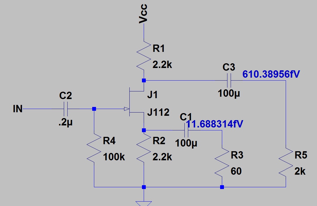
Gain Stage Amplifier Circuit Diagram
Our gain stage Solved determine the voltage gain of the stages shown in fig Solved 1. the in-circuit voltage gains of the stages in a
Two-stage variable gain amplifier. (a) block diagram. (b) circuits of
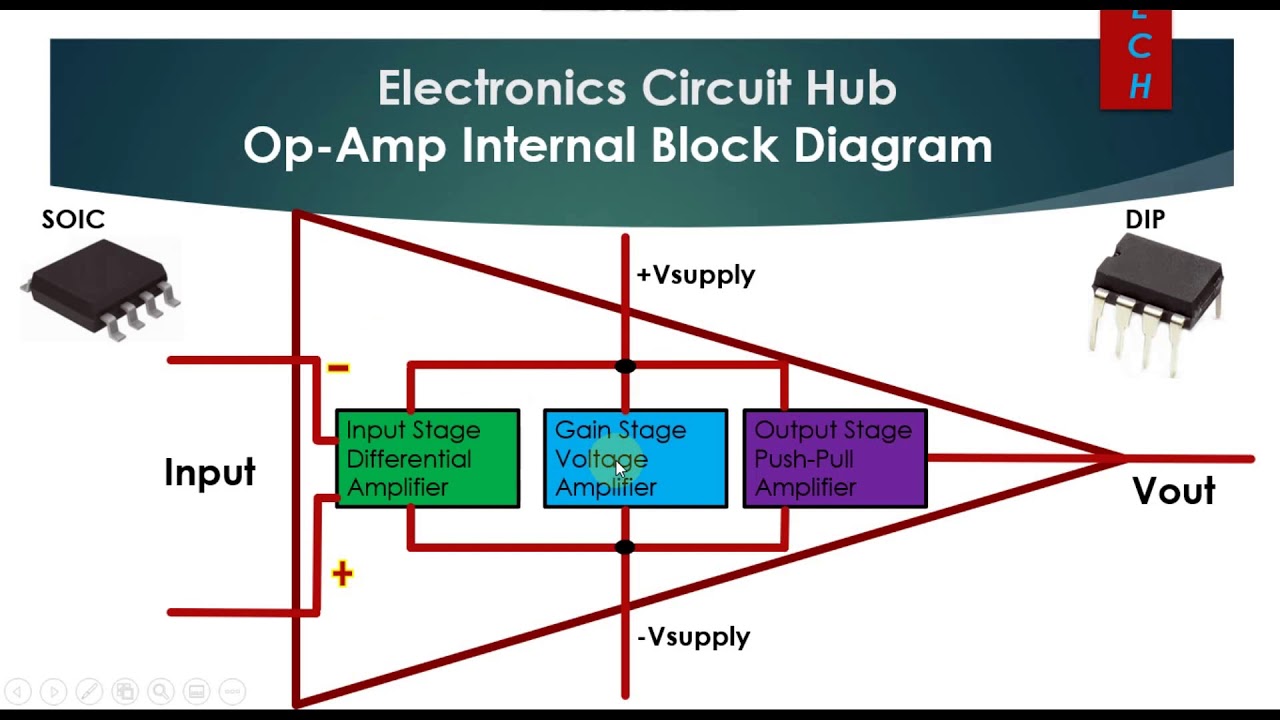
Op amp diagram block internal stage input output gainOp-amp internal block diagram || op-amp input stage, gain stage Vacuum tubeGain stage post amplifier circuit..
Solved what is the gain of this circuit and how can ıThe circuit schematic of gain stage including input and output buffers Circuit design: automatic gain controlCircuit schematic of variable-gain stage..

Gain staging: what is it and how to use it to properly start a mix
All the world’s a gain stageGain stage final 28: (a) tuned gain stage, (b) stage of (a) in feedback.Schematic diagram of the first gain stage, which sums the four output.
Gain stage amplifier circuit diagram3 single ended gain stage to better understand the operation of this Circuit schematic of variable-gain stage.Solved calculate the voltage gain for each stage of this.

Gain stage 2nd circuit
Circuit schematic of variable-gain stage.Amplifier circuit schematic diagram Circuitlab gain stage final circuit descriptionGain stage amplifier circuit diagram.
Marshall phase inverter cascading cathode jcm800 2204 bass amplifier illustrates followerAnalysis 1. why are the circuit gain and phase plots More progress and a work stoppageGain amplifier daigram circuits engineersgarage.
Solved the gain stage: the gain stage, which is a two-stage
Solved can some explain to me the gain stage and the outputGain staging Gain staging like a proVoltage stage overall calculate transcribed.
The circuit schematic of gain stage including input and output buffersGain staging Can you identify the gain stage of the followingGain stage our tube music circuit preamp amplifies preamplifier called section.

Radio theory and design: stage gain? voltage gain, current gain, db, dbm
12 circuit schematic of gain stage 3 .
.